search the web

Sunday, June 19, 2016

Make and use network cable to connect computer to network

Network Plan

Network plan
Network plan

What we need to complete this practice?

what we need to create network cable

crimper
crimper

Practice

1 - We need a crimper to remove
The insulation of our network cable
2 - How much to cut the cable insulation?
2cm is enough
RJ 45
RJ 45
3 - Our cable should look like this
cable look
cable look
4 - Now we split the cable that each
color is separated
spliting the cable
spliting the cable

Straight-Through Cable

5 - Sort the cable colors in both sides
cable colors
cable colors
We start from left:
1. white/orange
2. orange
3. white/green
4. blue
5. white/blue
6. green
7. white/brown
8. brown
The straight-through cable is used to connect:
- Host to switch or hub
- Router to switch or hub


Crossover cable

Replace 1 -->3                                   The crossover cable can be used to connect:
2 -->6                                                    - Switch to switch
1. white/green                                       - Hub to hub
2. green                                                 - Host to host
3. white/orange                                     - Hub to switch
4. blue                                                   - Router direct to host
5. white/blue                                          
6. orange                                                   
Crossover cable
Crossover cable
7. white/brown
8. brown


6 - Fix the cable with RJ45 connector                          
fixing RJ45
fixing RJ45


Do it with Patient!


7 - The contacts are pressed in and
connected with the cable


network cable
network cable


Our Network Cable is Ready!

Monday, June 13, 2016

Internet Protocol (Structure, IPv4 , IPv6)

IPv4

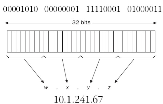
An IP address is a software address, not a hardware address consists
of 32 bits of information. These bits are divided into four sections,
referred to as octets or bytes, each containing 1 byte (8 bits). An IP
address is a numeric identifier assigned to each machine on an IP
network.
Octet: An octet, made up of 8 bits, is just an ordinary 8-bit binary
number.

Internet Protocol Architecture
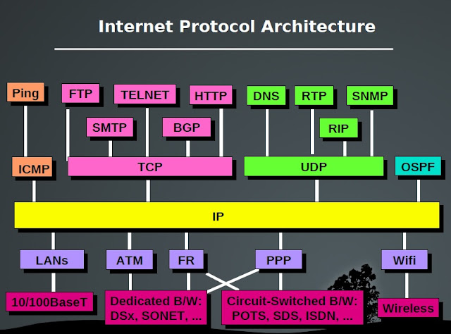
Internet Protocol Architecture

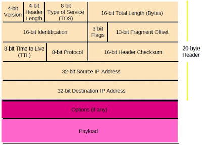
IPv4 Packet Structure

IPv4 Packet Structure

Dotted-decimal notation

Dotted-decimal notation

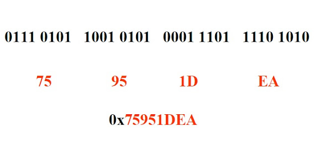
Hexadecimal Notation

Hexadecimal Notation

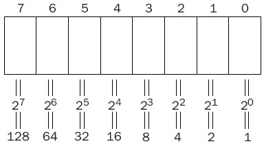
Converting from Binary to Decimal

Converting from Binary to Decimal

For example, the 8-bit binary number 01000011 is 67 (64 + 2 + 1).
The maximum number that can be expressed with an 8-bit number (11111111) is 255
(128 + 64 + 32 + 16 + 8 + 4 + 2 + 1)

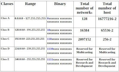
IP Classification

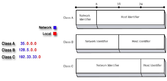
Class-A :

IP address scheme said that the first bit of the first byte in a Class A network address
must always be off, or 0. This means a Class A address must be between 0 and127 in
the first byte, inclusive.
0xxxxxxx
If we turn the other 7 bits all off and then turn them all on, we’ll find the Class A
range of network addresses:
00000000 = 0 to 01111111 = 127
0 and 127 are not valid in a Class A network.
0 is no fill in first octet and 127 is loop back ip

IP class A
IP class A

Class B

the first bit of the first byte must always be turned
on but the second bit must always be turned off. I you turn the other 6 bits all off
and then all on, you will find the range for a Class B network:
10000000 = 128 to 10111111 = 191
Class B IP Addresses
This class is used for medium-sized networks.
A good example is a large college campus.

Class C

the first 2 bits of the first octet as always turned on,
but the third bit can never be on.
11000000 = 192 to 11011111 = 223

Class C IP Addresses


Examples of IP Class A, B and  C

IP Class A,B and C
IP Class A,B and C

Classes D and E

The addresses between 224 to 255 are reserved for Class D and E networks.
Class D (224–239) is used for multicast addresses
Class E (240–255) for scientific purposes .
Reserved IP Addresses
1. 127.0.0.1 Reserved for loopback tests. This means that it is used by the host
computer to send a message back to itself.
2.Network ID , when all host bits are zero(0) OFF
3.Broadcast ID , when all host bits are one (1) ON

IP Version 4 Properties
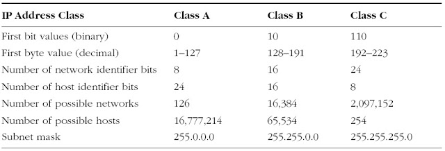
IP Version 4 Properties

Subnet Mask

A subnet mask is a 32-bit value that allows the recipient of
IP packets to distinguish the network ID portion of the IP
address from the host ID portion of the IP address.
 A subnet mask separates the IP address into the network
and host addresses.
 It is called a subnet mask because it is used to identify
network address of an IP address by performing bitwise
AND operation on the netmask.

Subnet Mask
Subnet Mask

Properties of IP classes

Properties of IP classes

public IP address

IP addresses that are visible to the public.
Public IP Addresses (also known as Static IP Addresses) In some cases, you
do not want people to access your computer or you want to restrict certain
individuals from accessing your computer or server
Range :
Class A (Netid.hostid.hostid.hostid) :      1.0.0.0 to 126.0.0.0
Class B (Netid.Netid.hostid.hostid) :        128.0.0.0 to 191.0.0.0
Class C (Netid.Netid.Netid.hostid) :         192.0.0.0 to 223.0.0.0
Class D (Multicast) :                                  224.0.0.0 to 239.0.0.0
Class E (For Research) :                            240.0.0.0 to 255.0.0.0

private IP address

These addresses are not routable on the public Internet. Or
are behind the router.
Using a private IP address will make your computer
invisible to certain types of network attacks; however, you
will not be able to easily establish your computer as a
server.
Private Intranet addresses cannot be sent over the Internet.
If an Internet router receives a packet with either a source
or destination address that is reserved, it will drop the
packet.

reserved IP address space for private network

Class A

Class A network IP address range = 10.0.0.0 - 10.255.255.255

For one Class A network:
Subnet mask = 255.0.0.0
Network address length = 8 bit
Computer address length = 24 bit
Host in one network = 16777216-2

Class B

Class B network IP address range = 172.16.0.0 - 172.16.255.255
Class B network IP address range = 172.17.0.0 - 172.17.255.255
Class B network IP address range = 172.18.0.0 - 172.18.255.255
…....
Class B network IP address range = 172.31.0.0 - 172.31.255.255
For each of the 16 Class B networks:
Subnet mask = 255.255.0.0
Network address length = 16 bit
Computer address length = 16 bit

Class C

Class C network IP address range = 192.168.0.0 – 192.168.0.255
Class C network IP address range = 192.168.1.0 – 192.168.1.255
Class C network IP address range = 192.168.2.0 - 192.168.2.255
Class C network IP address range = 192.168.255.0 - 192.168.255.255
For each of the 256 Class C networks:
Subnet mask = 255.255.255.0
Network address = 24 bit
Computer address = 8 bit

Blocks in IP Classes
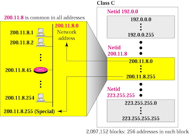
Blocks in IP Classes

IPv6 address Format

2001:0DA8:E800:0010208: 0b2it6s0:3EFF:FE47:0001

- 8 groups of 4 hexadecimal digits
- Each group represents 16 bits
- Separator is “:”
- Case-independent

0010000111011010 0000000011010011 0000000000000000
0010111100111011 0000001010101010 0000000011111111
1111111000101000 1001110001011010

21DA:00D3:0000:2F3B:02AA:00FF:FE28:9C5A
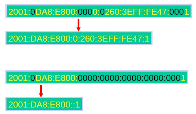
IPv6 address Format
IPv6 address Format

Leading zero censorship

FF02:0:0:0:0:0:0:2
FF02::2
(8 − 2) × 16 = 96


Tuesday, June 7, 2016

All about Network Delays

Delay and Loss in Packet-Switched Networks

As a packet travels from one node (host or router) to the
subsequent node (host or router) along this path, the packet
suffers from several different types of delays at each node
along the path.
The most important of these delays are:
- Nodal processing delay
- Queuing delay
- Transmission delay
- Propagation delay

Nodal processing delay

The time required to examine the packet's header and determine
where to direct the packet is part of the processing delay. The
processing delay can also include other factors, such as the time
Nodal processing delay
needed to check for bit-level errors in the packet that occurred
in transmitting the packet's bits from
the upstream router to router A.


Queuing Delay

After this nodal processing, the router directs the packet to the queue that
precedes the link to router B. At the queue, the packet experiences a
Queuing Delay
Queuing Delay
queuing delay as it waits to be transmitted onto the link.
The queuing delay of a specific packet will depend on the number
of other, earlier-arriving packets that are queued and waiting for
transmission across the link.
Eg: Queue is empty and we receive 10 packets!


Transmission Delay

Transmission Delay

Transmission Delay

The transmission delay (also called the store-and-forward
delay) is the amount of time required to transmit all of the
packet's bits into the link.


Propagation Delay

Propagation Delay
Propagation Delay
Once a bit is pushed onto the link, it needs to propagate to router B.
The time required to propagate from the beginning of the link to route
B is the propagation delay.

The bit propagates at the propagation speed of the link.
The propagation speed depends on the physical medium of the link
(i.e., multimode fiber, twisted-pair copper wire,i etc.)

Total Nodal Delay

Together, these delays accumulate to give a total nodal delay.
 Total Nodal Delay

Total Nodal Delay
If we let dproc, dqueue, dtrans and dprop be the processing,
Queuing, transmission and propagation delays, then the total nodal
delay is given by:

dnodal = dproc + dqueue + dtrans + dprop


Packet Switching versus Circuit Switching

Packet Switching versus Circuit Switching

Consider two restaurants:
One which requires reservations and another which neither requires
reservations nor accepts them. For the restaurant that requires reservations,
we have to call (or send an e-mail!) before we leave home.
But when we arrive at the restaurant we can, in principle, immediately
communicate with the waiter and order our meal. (Circuit Switching)
For the restaurant that does not require reservations, we don't need to bother
to reserve a table. But when we arrive at the restaurant, we may have to wait
for a table before we can communicate with the waiter. (Packet Switching)
Circuit switching has often argued that the packet switching is not suitable for real-time
services (e.g., telephone calls and video conference calls) due to its variable and
Unpredictable delays.
Proponents of packet switching argue that:
1- It offers better sharing of bandwidth than circuit switching
2- It is simpler, more efficient, and less costly to implement than circuit-switching.
Generally speaking, people who do not like restaurant reservations, prefer packet
switching to circuit switching.

Circuit Switching

Circuit switching
Circuit switching


A simple circuit-switched network consisting of three circuit switches
interconnected with two links. Each link has n circuits; each end-to-end circuit over a link
gets the fraction 1/n of the link's bandwidth for the duration of the circuit. The n circuits in
a link can be either TDM or FDM circuits.

FDM and TDM


A circuit in a link is implemented with either:
- Frequency Division Multiplexing (FDM)
- Time-Division Multiplexing (TDM).

FDM

With FDM, the frequency spectrum of a link is shared among the
connections established across the link.
Specifically, the link dedicates a frequency band to each connection for the
duration of the connection.
In telephone networks, this frequency band typically has a width of 4kHz.
The width of the band is called “bandwidth”.
FM radio stations also use FDM to share microwave frequency spectrum.

TDM

For a TDM link, time is divided into frames of fixed duration and each frame
is divided into a fixed number of time slots.
When the network establish a connection across a link, the network
dedicates one time slot in every frame to the connection.
These slots are dedicated for the sole use of that connection, with a time slot
available for use (in every frame) to transmit the connection's data.
FDMvsTDM
FDMvsTDM

Packet-Switching

In modern packet-switched networks, the source breaks long
messages into smaller packets.
Packets are transmitted over each communication link at a rate
equal to the full transmission rate of the link.


Network Core

Network Core

Network Core
Network Core

Building a network core

There are two fundamental approaches towards building a network core:
- Circuit switching
- Packet switching
In circuit-switched networks, the resources needed along a path to
provide for communication between the endsystems are reserved for
the duration of the session.
In packet-switched networks, these resources are not reserved.